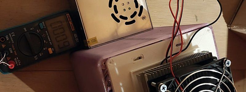
60 hours of printing. About 850 g of PETG. Eight tiny brass inserts. 9 °C on the multimeter after 40 minutes. And the first can is not cold yet.
This is my 3D-printed frigo (mini fridge) for one can of soda. It is an alpha of a prototype: everything is printed and assembled, and the measurements are only starting. So this post is about how it was made, and how much of it was done by AI agents. A lot, and not without mistakes.
In French, « souffler le chaud et le froid » (« blow hot and cold ») means to keep changing your mind. My box does it for real: hot air goes up, cold air goes down.
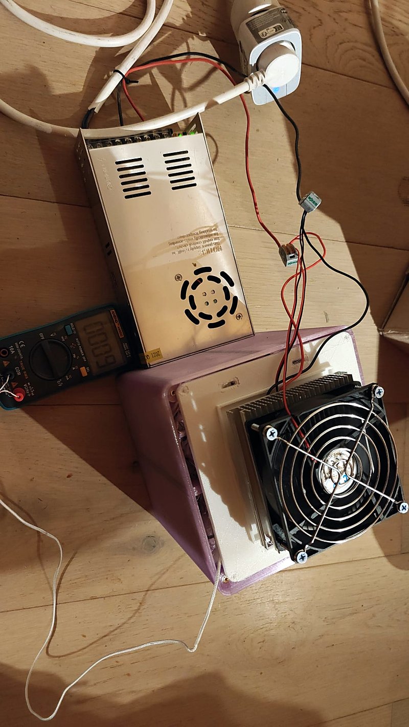
What is inside
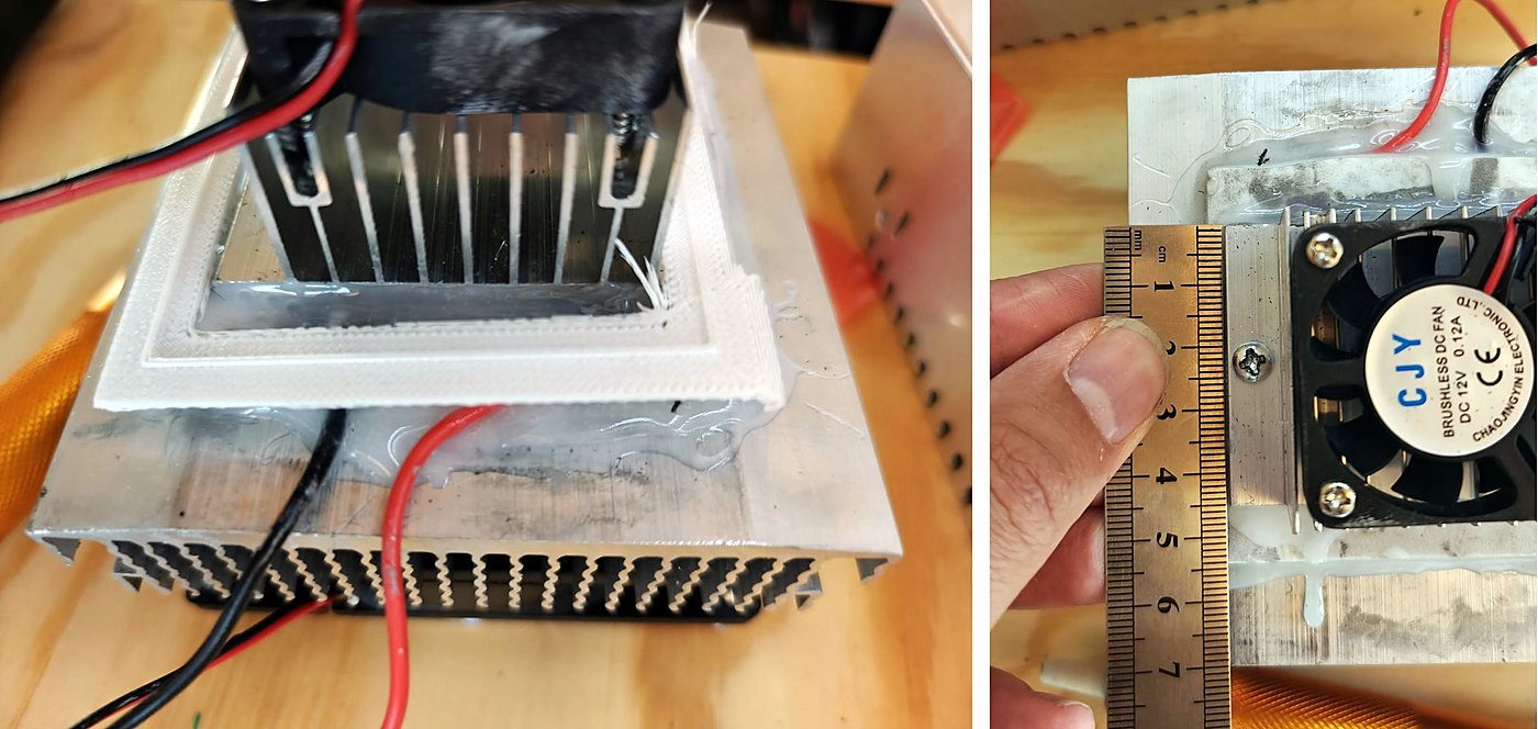
- A « 50 W » Peltier kit (TEC1-12706, 12 V): big heat sink and fan on the hot side, a small finned block and a 40 mm fan on the cold side. Already assembled and sealed with silicone: no disassembly.
- A 360 W 12 V power supply.
- A box that I print, with the kit as its roof. The hot side stays outside and blows up. The cold block goes inside, and its fan blows cold air down on the can. The can never touches the Peltier.
That last idea was mine. It matters in a minute.
Un froid de canette
I started with a chat with Gemini. Its two answers did not agree: in open air the module was « at 100 % », in a closed box it reached « 2 °C at 30 °C ». It also assumed a power that nobody had measured.
So I gave the chat and my photos to Claude Code, and it wrote its own model: the Peltier equations, calibrated on my only three numbers (hot sink 34 °C, cold sink 12 °C, room 21 °C). First answer: an empty, insulated box can get down to a few degrees, even at 30 °C. But the can is the problem, not the Peltier. A 33 cl can gives its heat to still air very slowly.
The agent had assumed that the can touches a cold metal cradle. I said no: air only. It ran the model again:
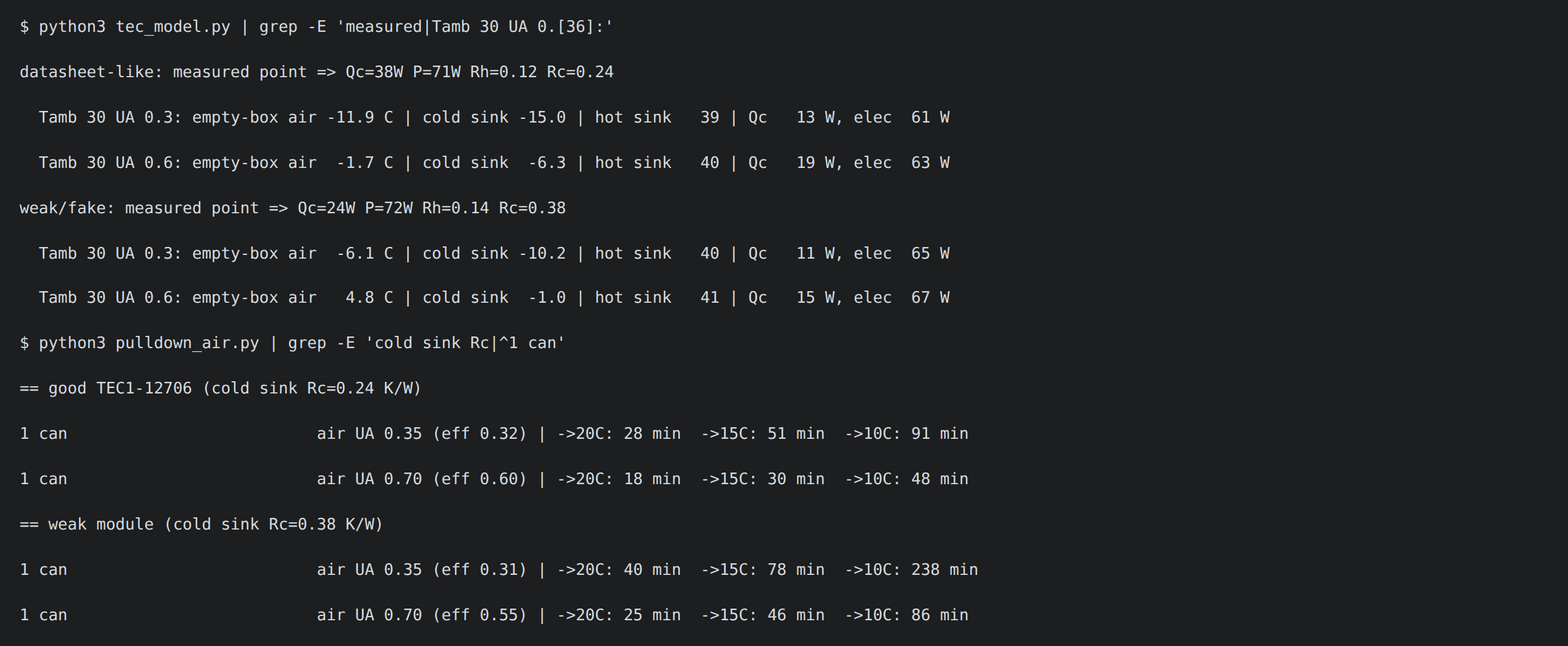
One can from 30 °C to 15 °C: 30 to 51 minutes with a good module, 46 to 78 with a weak one. Later reviews said that even this is optimistic, and that 15 °C is « a coin flip ». We will see.
A ruler, a phone and a 10-minute print
I could not open the kit, so the agent measured it from my photos, with a ruler held next to each part. Result: within 3 to 5 mm (the ruler was not in the same plane as the part, so the photos lie a little).
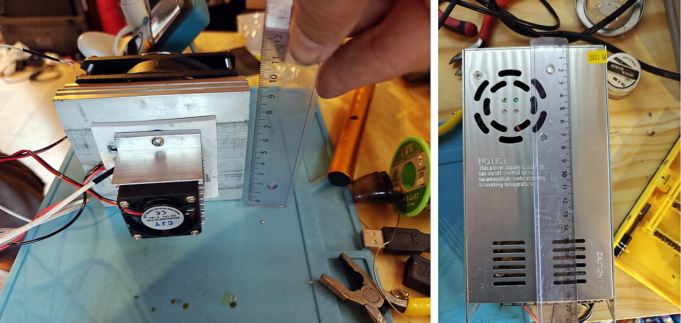
Then a cheap test: a 10-minute printed « gauge » to check that the cold block goes through the roof window. It did, but not the aluminium plate behind it (60 mm, for a 50 mm window). The window became 66 x 52 mm.
Design in code
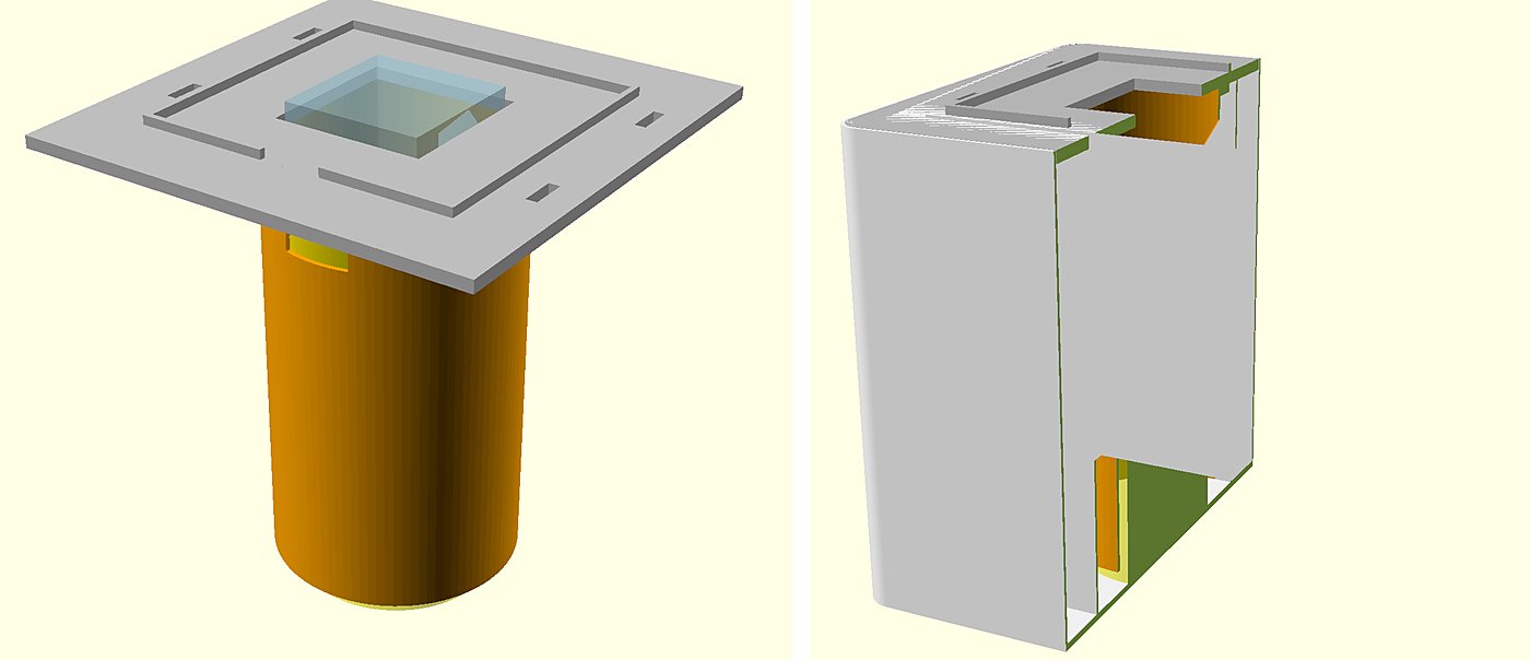
The whole design is one OpenSCAD file: change a number, every part follows.
- Roof: a plate with the window and four M3 heat-set inserts.
- Body: a double-wall box. The inner wall is watertight (condensation), the outer wall is pretty, and between them is a 20 mm cavity for four layers of aluminium bubble foil, hidden from view. The agent estimated the heat leak at 0.2 W/K.
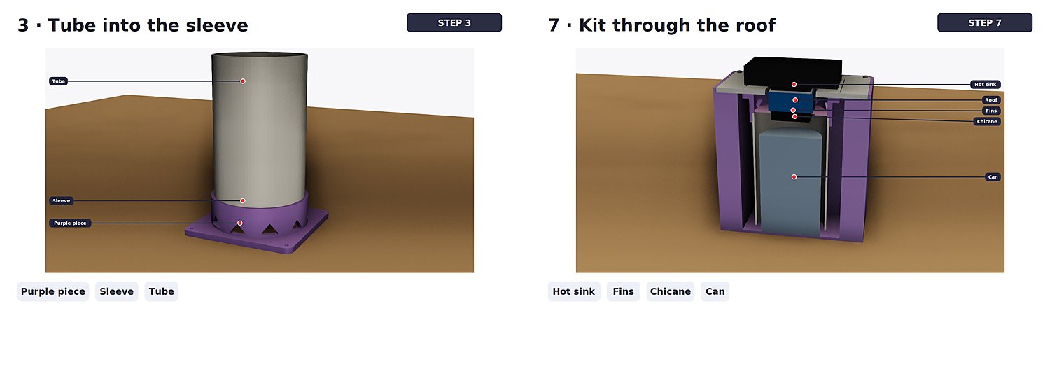
- Collar and baffle: the collar holds a pipe and has windows where the cold air comes back up. The baffle closes the gap around the fan, so the air has to go down.
Before every print, the agent ran a preflight on my home server: a support check, a headless slicer, about 30 checks.
Sang-froid
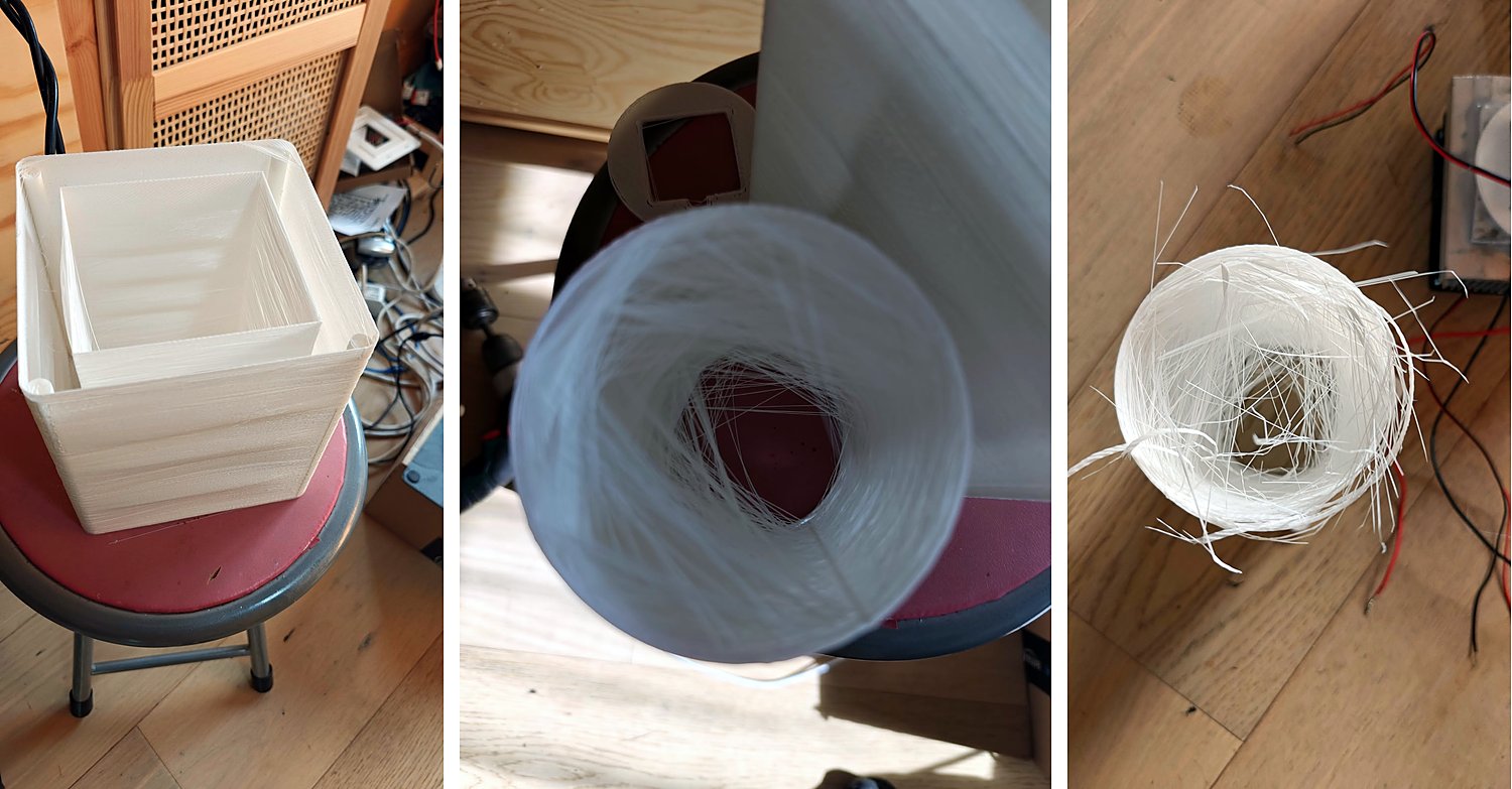
The first body was white PLA+, with a hollow printed tube for the air. It was thin. Too thin. And the tube grew a web of strings inside, so many that I could not clean it without breaking it.
Before printing more, I asked two other agents (Claude Sonnet) for a counter-review: one on the strength, one as devil’s advocate on the whole design. They found:
- An air short circuit: a free gap of 2,700 mm² let the cold air go back up without passing the can. The fix is a flat ring on the fan, a baffle. In French, « chicane » means a baffle, and also a quarrel. Between the air and the can, there was one.
- Windows too small: 461 mm² for a fan that needs about 1,000.
- A wrong gap between the can and the fan: 17 mm, not 12.
- A thermal estimate too optimistic: my kit looks like a weak module.
My brief for the next version was short: strong, and I do not care how long it takes. So: PETG (240 °C, bed at 85 °C), walls of 3 mm, and no printed tube. I had a rigid pipe at home (76 mm inside, 80 mm outside). I cut it to 131 mm, within 1 mm, and the agent designed a short printed collar to hold it.
60 hours
The body took 3,631 minutes on my Artillery Sidewinder X2: about 60 hours. During a long night print, the agent checked the camera and the printer every 16 minutes, looking for lifted corners and strings.
One bug almost cost me those 60 hours. The first PETG collar and baffle weighed 24 g, and they should have weighed 65 to 70 g. The slicer had silently ignored my filament diameter (1.75 mm) and computed for 2.85 mm: the extrusion was only 38 % of what it should be. A thin wall at 38 % does not look wrong. It is just weak.
We found it by weighing a test cube (2.3 g predicted, 6.1 g expected), fixed the command, and printed a new cube: 6 g. Then the body. The rule is now written in the repo: compare the predicted mass with the real volume before every big print.
Chaud devant
Some time later I came back to the parts and had forgotten how they fit together. I asked for « a simple diagram ». It took three tries.
- A text answer and a French diagram. I understood nothing.
- Ten flat pages in English, one per step. « Really not clear. »
- My idea: « 3D renders with local tools, something more realistic. » The agent exported each part from the OpenSCAD file, built one scene per step, and rendered them offline with f3d. The colours come from my photos. The labels are piece names, and nothing else.
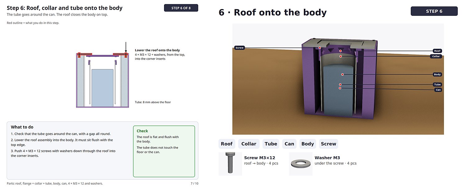
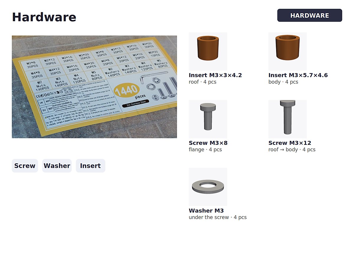
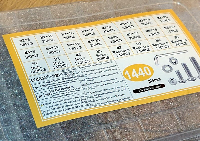
Then I asked which inserts and screws I need at each step, and what a bolt is called. (A screw goes into an insert. A bolt goes through and needs a nut. Here: only screws, washers and inserts.) The agent added a hardware page with a photo of my screw box.
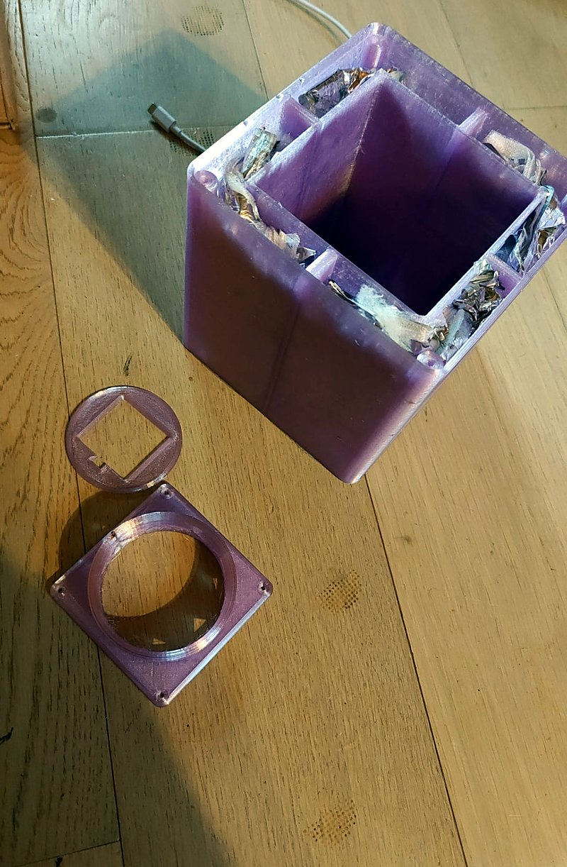
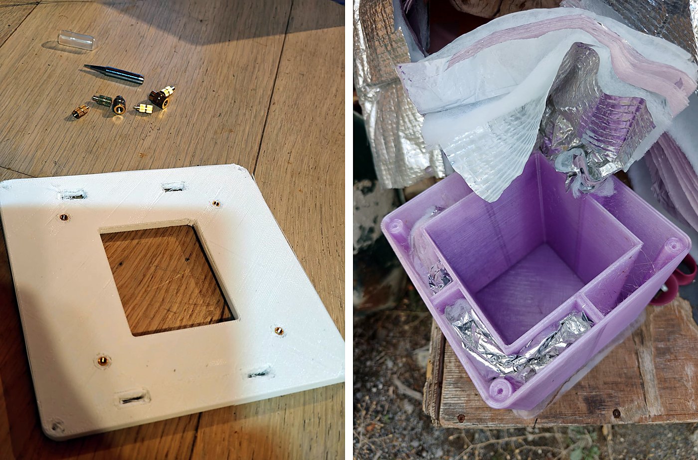
Meanwhile, real photos of the assembly:
Where it stands
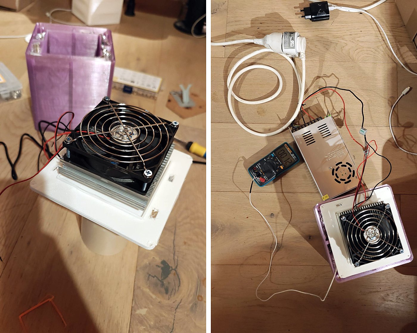
The box is assembled: inserts in the roof and in the body, foil in the cavity, the kit on the roof, and a power supply with a multimeter next to it.
First sign of life: about 40 minutes after power on, the multimeter reads 9 °C, in a room at 21.7 °C (my baseline). My model says an empty box should end below 0 °C in a 21 °C room. The real box has a bare roof and floor, and it is only 40 minutes in, so we will see where it settles. No can yet.
Still to do:
- measure the real current (weak module or good one?)
- a real test with a real can
- a thermal fuse on the hot sink, in case its fan stops
- insulate the roof and the floor, and seal with silicone
The result, good or bad, may become a second post.
How AI was used
Almost all the engineering was done with AI agents (Claude Code), on my desktop and my home server.
Who did what
- The agent: re-checked the Gemini maths, wrote the thermal model and the simulations, took dimensions from my photos, wrote the OpenSCAD design, sliced, launched and watched the prints, and made the manual.
- Two more agents: the counter-reviews.
- A notes file: every mistake became a written rule that the next agent reads first.
What the agents got wrong
- The first model: the can on a cold cradle, and a module as good as its datasheet.
- A cold-air window at the level of the fan, so the air left at once. Windows too small. A plate that did not fit the gauge.
- The 38 % under-extrusion.
Most of these were caught by a second agent, a test print, a scale or me.
What I did
- The architecture: hot up, cold down.
- Photos, rulers, the pipe and its cut at 131 mm.
- « Strong, not fast. » PETG, and « go » on every print.
- The glue, the inserts, the screws, the assembly.
- Saying « I don’t understand that » until the manual became real 3D renders.
Note: I don’t have much time for the blog these days, so this post was written with the help of an AI, from my own notes, then read and corrected by me. Better to share the content this way than not at all.