Bonjour, un article un peu spécial, puisqu’il s’agit d’un copie colle d’un article (assez ancien) fait dans le cadre d’un club maker dont je fais parti:
Goal is to present a bit what we did, what we have, what we’re aiming at in the short term..
Our first project
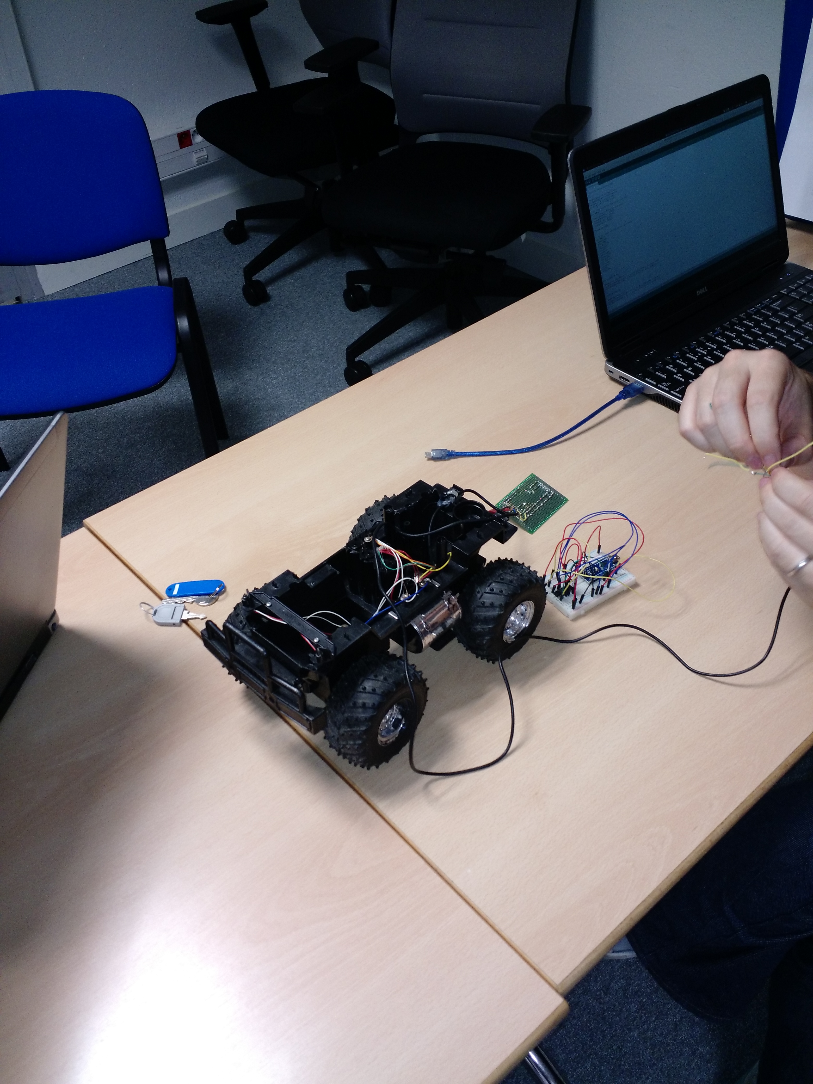
One of the toy attracted us, this one:
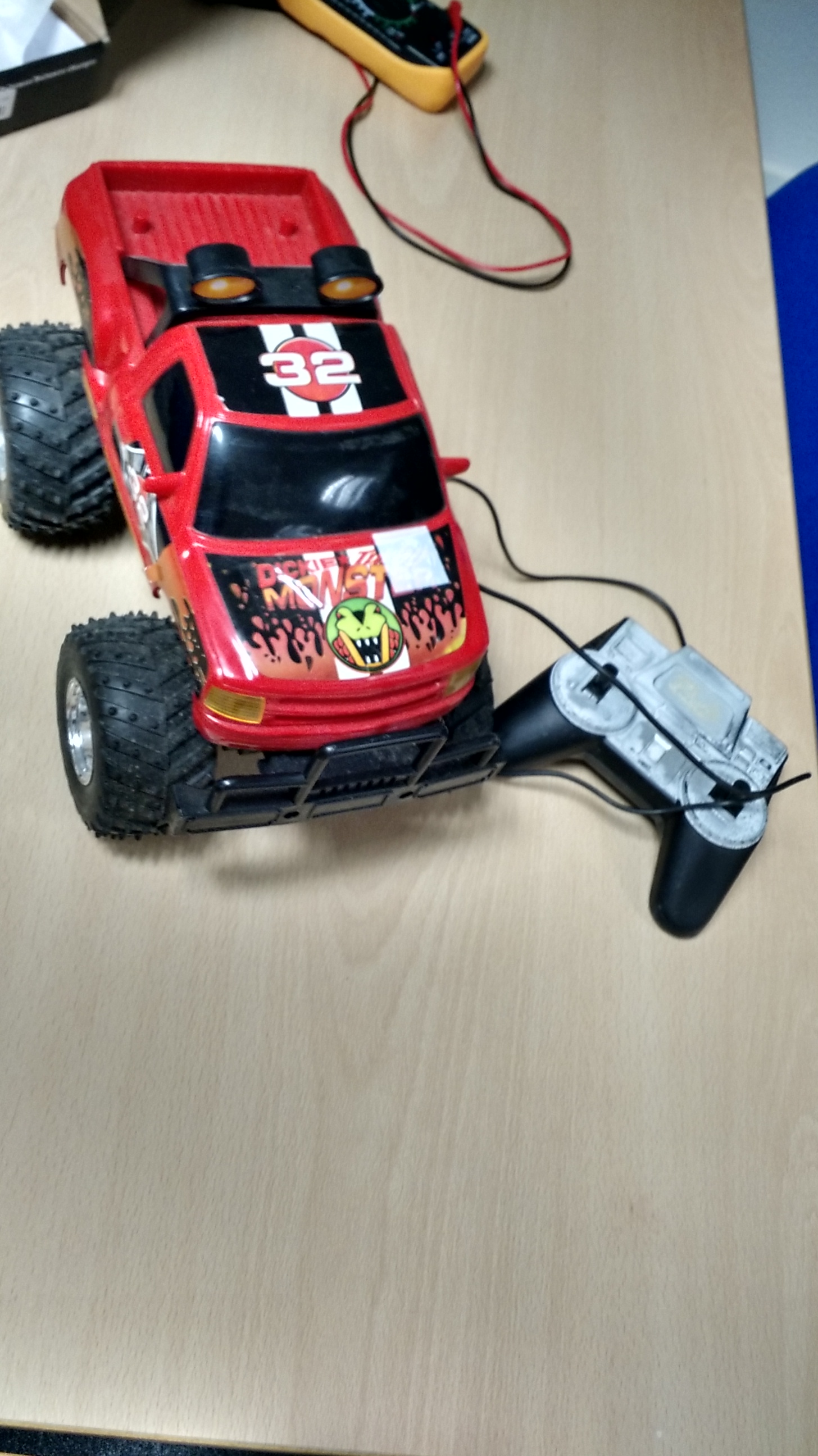
Our goal was clear, reviving this buggy and making it autonomous using an arduino.
First, after taking it apart, we tried to understand the original – simple – design:
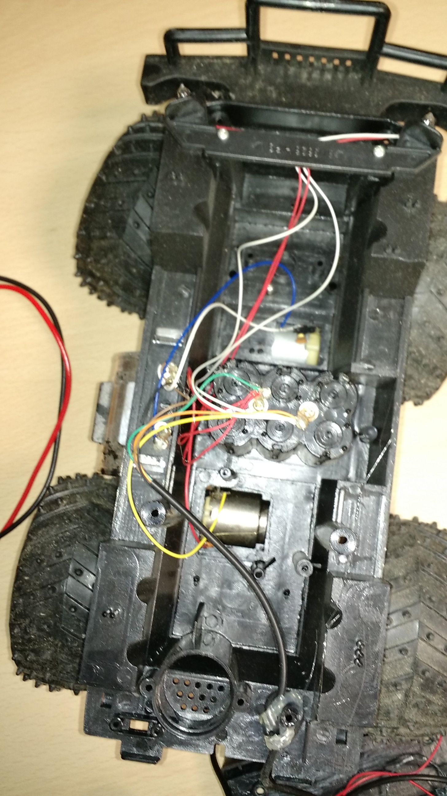
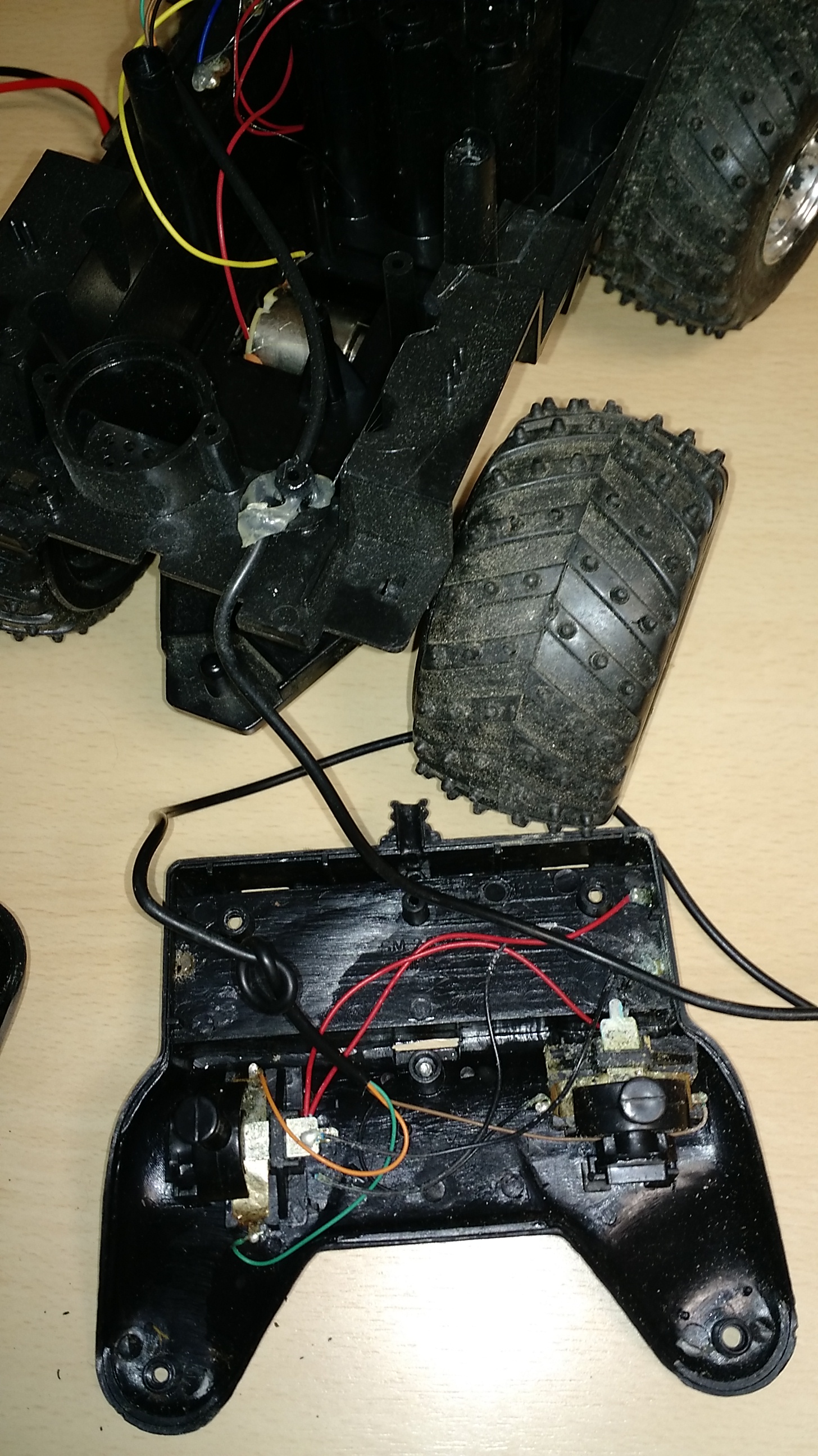
But also that many wires were corroded making the car useless in its current condition.
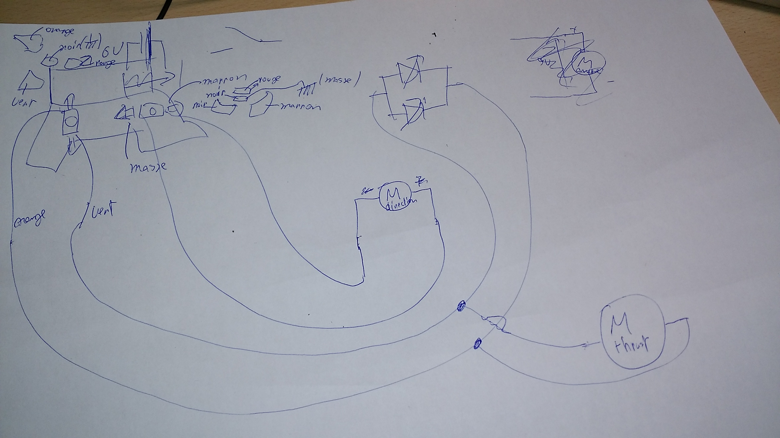
Turned into this hand-made drawing schematics:
First, we tried to control the 6V 250ma DC motor via the TTL voltage given by arduino outputs using the only transistor we had,at this time an IRF520N (here).
Which we hooked to a 12V battery + DC motor:
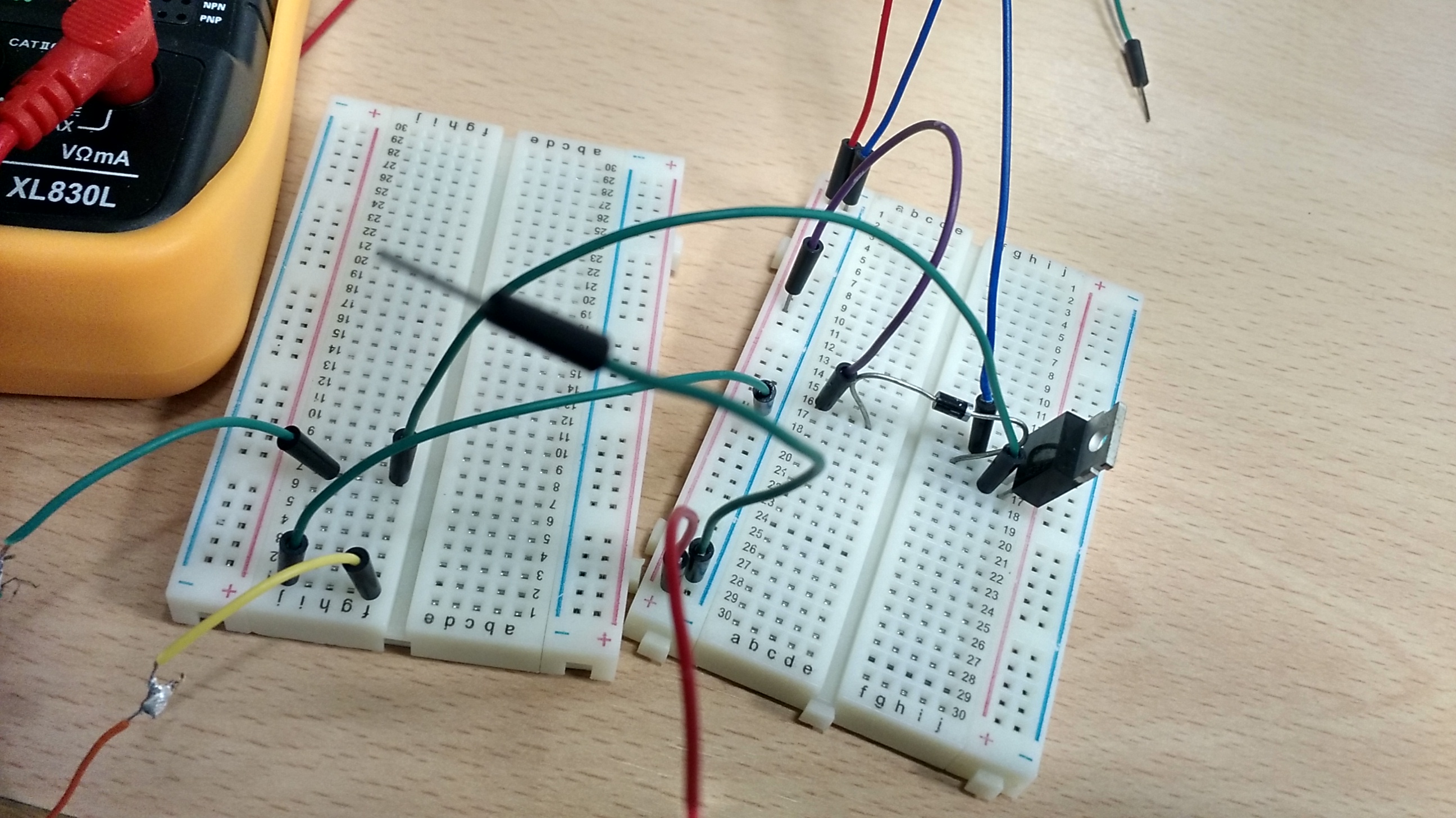
But we didn’t get the results we expected,indeed motor was running very weakly, plus the transistor was getting very hot.
After some thoughts, we concluded looking at specs (page 3, characteristics graph on bottom left) that even if the graph is based on Vds = 50V, the Vgs we put is too low, as a consequence transistor is not « fully » in court circuit state (« passant ») => big internal resistance => big voltage. Also, current at this regime is low, thus low rpms. We needed 10V on the gate to have it working in its nominal regime, that’s much more than TTL arduino levels (5V).
So we ordered another transistor better suited for our low activation voltage.
At some point, we wanted to control both front motor (for steering) and rear motor (to move forwards/backwards).
So we ordered a LS293 component, containing 2 H bridges, but only after one of us reinvented H bridge principle.
We wanted to jump from breadboard prototyping to PCB soldering prototyping cards..
As we lacked experience in PCB prototype board usage at this point, our first attempt was a bit laborious and not the cleanest imaginable (from now on we’ll avoid soldered tracks):
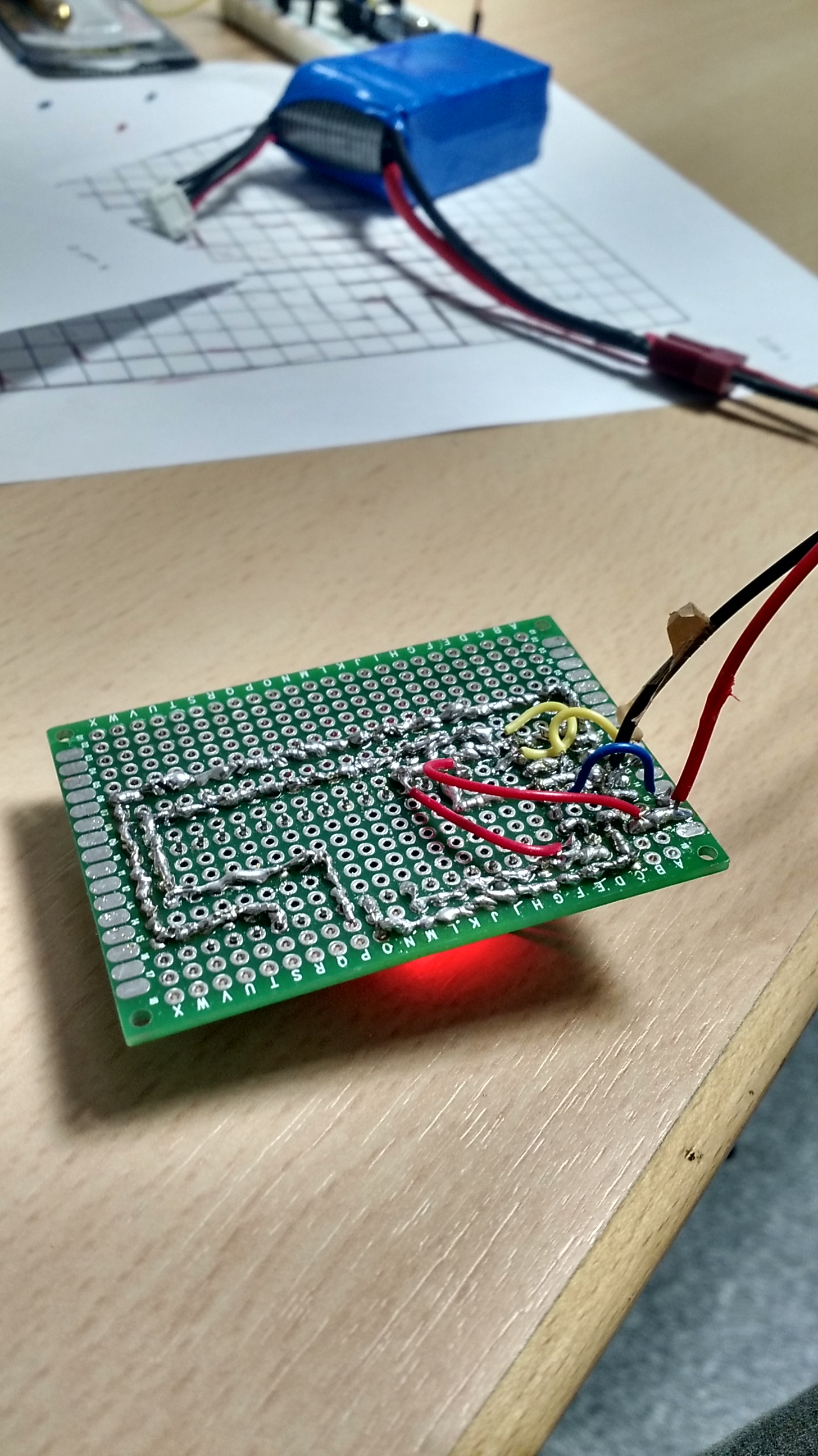
But was functional!
… until the LS293 exploded..
We were a bit too excited to test the whole thing, that we bypassed basic checks such as how much current motors were asking for, and LS293 temperature.
It happened that an adhoc repair we did for the steering prevented the front motor from moving freely, and additional torque made the motor take more current than preliminary tests.
=> we went well beyond internal LS293 h-bridges max current specs
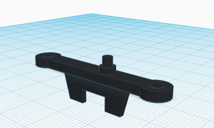
Consequence:
- we modelised and 3d printed the broken part to have cleaner repair:
- we realised our original schematics could be improved by enlarging ground plane, also used to dissipate heat
- maybe we should use a DC motor with max current usage within our LS293 specs

- maybe we should use a servo/step motor, much better suited for steering than original DC motor
and here we are now, we’ll be back with latest updates!
Next steps
Once we have all basics working for our car, we want to plug one of the many sensors we have (ultrasonic, rgb, we have wide angle camera with RF transmission..), put basic AI (fitting in arduino’s atmel cpu), then using advanced controller (possibly configured via openpilot) and more advanced stuff (remote control via reinforcement learning running on PC..).